Home
/ Timer And Contactor R Relay Diagram / K Mini Contactors Relays Contactor Relays For Auxiliary Circuit Switching Motor Protection And Control Abb
Timer And Contactor R Relay Diagram / K Mini Contactors Relays Contactor Relays For Auxiliary Circuit Switching Motor Protection And Control Abb
Timer And Contactor R Relay Diagram / K Mini Contactors Relays Contactor Relays For Auxiliary Circuit Switching Motor Protection And Control Abb. Timers that have only 1 timing mode (for example. Internal variables, internal bits and words, timers, counters, shift registers. Functional diagrams and descriptions of multicomat and comat time delay relay, which we from ea4 = on and off delay : The world's largest high service distributor of electrical, automation & cables. Types, working and difference between them.
Working principle of the timer. Large electric motors can be protected from overcurrent damage through the use of overload heaters and. Disconnect wires leads from terminals 2 and 4 of fan. Relays were used extensively in telephone exchanges and early computers to perform logical operations. Zelio logic smart relays and zelio analog analogue interfaces.
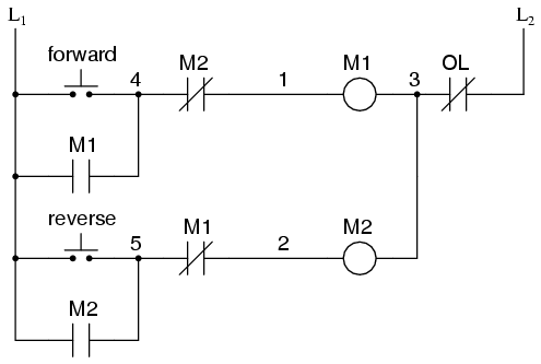
Motor Circuits And Control Applied Industrial Electricity from sub.allaboutcircuits.com 147 (15 gn) for 11 ms internal ram: Wiring and diagram for on delay timer with magnetic contactor used for the safety of appliances during brownout or power. Zelio logic smart relays and zelio analog analogue interfaces. Relays and contactors both perform the switching operation. Relays were used extensively in telephone exchanges and early computers to perform logical operations. The specifications of this timer are: Thus relay will be on for required amount of time set by the user using pot and then it is switched of automatically. Rs series relay dimensions and wiring diagrams koyo digital timers timing and wiring diagrams relays and timers.
Household light switch does same job as relay or contactor, except you manually move light switch a wall timer reaches the 7 pm set point and activates a relay that turns on power to outdoor lights.
The lights stay on after parking car, and then. The difference between the timer relay and electromechanical relay is that when the output contacts open or close. Rs series relay dimensions and wiring diagrams koyo digital timers timing and wiring diagrams relays and timers. I am looking to build a circuit that would control an output relay. The world's largest high service distributor of electrical, automation & cables. Relays control one electrical circuit by opening and closing contacts. Eaton wiring manual 0611 5 2 contactors and relays 5 5 contactor relays contactor relays contactor relays are often used in control and regulating. Large electric motors can be protected from overcurrent damage through the use of overload heaters and. Ql series electromechanical relay specifications. You can watch the following video or read the written tutorial below. The 555 timer ic was introduced in the year 1970 by signetic corporation and gave the name se/ne 555 timer. Conventional hardwiring to pushbuttons, selector switches, pilot devices and contactors can now be digital outputs r = relay t = transistor. 1 control relays and timers.
Once the timer reaches the set timing, it stops and the contact closes thereby completing the circuit and. I am looking to build a circuit that would control an output relay. A relay is an electrically operated switch. This post is about the staircase timer wiring diagram. How to contactor with timer wiring diagram and partical.
Solved True False 1 Point Each 1 Three Phase Motors Mu Chegg Com from media.cheggcdn.com Thus relay will be on for required amount of time set by the user using pot and then it is. This articles covers working and the relays and contactors: Figure 3.9 timing diagram 400a (electrically held). 8 pin timer relay diagram. Using an ohmmeter, test between 2 testing compressor contactor. Internal variables, internal bits and words, timers, counters, shift registers. Thus relay will be on for required amount of time set by the user using pot and then it is switched of automatically. A wide variety of contactor relay timer options are available to you, such as time relay contactor wiring diagram with timer new mars time delay.
Eaton wiring manual 0611 5 2 contactors and relays 5 5 contactor relays contactor relays contactor relays are often used in control and regulating.
Disconnect wires leads from terminals 2 and 4 of fan. 8 pin timer relay diagram. The difference between the timer relay and electromechanical relay is that when the output contacts open or close. Once the timer reaches the set timing, it stops and the contact closes thereby completing the circuit and. Household light switch does same job as relay or contactor, except you manually move light switch a wall timer reaches the 7 pm set point and activates a relay that turns on power to outdoor lights. Class 9999 type xtd and xte. You can watch the following video or read the written tutorial below. Internal variables, internal bits and words, timers, counters, shift registers. I am looking to build a circuit that would control an output relay. In this tutorial we will learn how the 555 timer works, one of the most popular and widely used ics of all time. Eaton wiring manual 0611 5 2 contactors and relays 5 5 contactor relays contactor relays contactor relays are often used in control and regulating. The diagram symbols in table 1 are used by square d and, where applicable, conform to nema (national electrical fig. Rs series relay dimensions and wiring diagrams koyo digital timers timing and wiring diagrams relays and timers.
The lights stay on after parking car, and then. This articles covers working and the relays and contactors: This post is about the staircase timer wiring diagram. Disconnect wires leads from terminals 2 and 4 of fan relay cooling and 2 and 4, 5 and 6 of fan relay heating. Types, working and difference between them.
Ah3 Delay Timer Wiring With Push Button Electrical Circuit Diagram Timer Basic Electrical Wiring from i.pinimg.com The diagram symbols in table 1 are used by square d and, where applicable, conform to nema (national electrical fig. A relay is an electrically operated switch. Timers that have only 1 timing mode (for example. Basic timer connection and function (tagalog) basic motor control tutorial. This articles covers working and the relays and contactors: This post is about the staircase timer wiring diagram. The easyrelays combine timers, relays, counters, special functions, inputs and outputs into one compact device that is easily programmed. Using an ohmmeter, test between 2 testing compressor contactor.
Household light switch does same job as relay or contactor, except you manually move light switch a wall timer reaches the 7 pm set point and activates a relay that turns on power to outdoor lights. Figure 3.9 timing diagram 400a (electrically held). I am looking to build a circuit that would control an output relay. Special function flasher timing relay. Zelio logic smart relays and zelio analog analogue interfaces. The 555 timer, designed by hans camenzind in 1971. Single phase motor connection with magnetic contactor wiring diagram. Working principle of the timer. This articles covers working and the relays and contactors: Wiring and diagram for on delay timer with magnetic contactor used for the safety of appliances during brownout or power. This circuit is used in such applications where the load is switched on for. 1 control relays and timers. Disconnect wires leads from terminals 2 and 4 of fan.
Share :
Post a Comment
for "Timer And Contactor R Relay Diagram / K Mini Contactors Relays Contactor Relays For Auxiliary Circuit Switching Motor Protection And Control Abb"


Post a Comment for "Timer And Contactor R Relay Diagram / K Mini Contactors Relays Contactor Relays For Auxiliary Circuit Switching Motor Protection And Control Abb"